

Direct-to-Chip Liquid-Cooling Guide
Pressure Decay vs Trace Gas for Direct-to-Chip Liquid Cooling
Published October 21, 2026 · Trace Gas Leak Testing · Zaxis
Select a production leak-test sequence from the contained volume, required evidence and available cycle time—not from a method label.
Cold plates, coolant distribution units and connected loops put a contained fluid path beside high-value electronics. A production test needs to answer whether the sealed boundary meets its documented requirement, while a diagnostic step may need to identify where a failure is located.
Air leak testing and trace-gas leak testing are peer method families under Leak Testing. For many direct-to-chip parts, the practical answer is a two-stage sequence: use an air method for a fast, dry production screen, then use trace gas when the limit or failure analysis requires finer detection or a location.
Start with the measured boundary
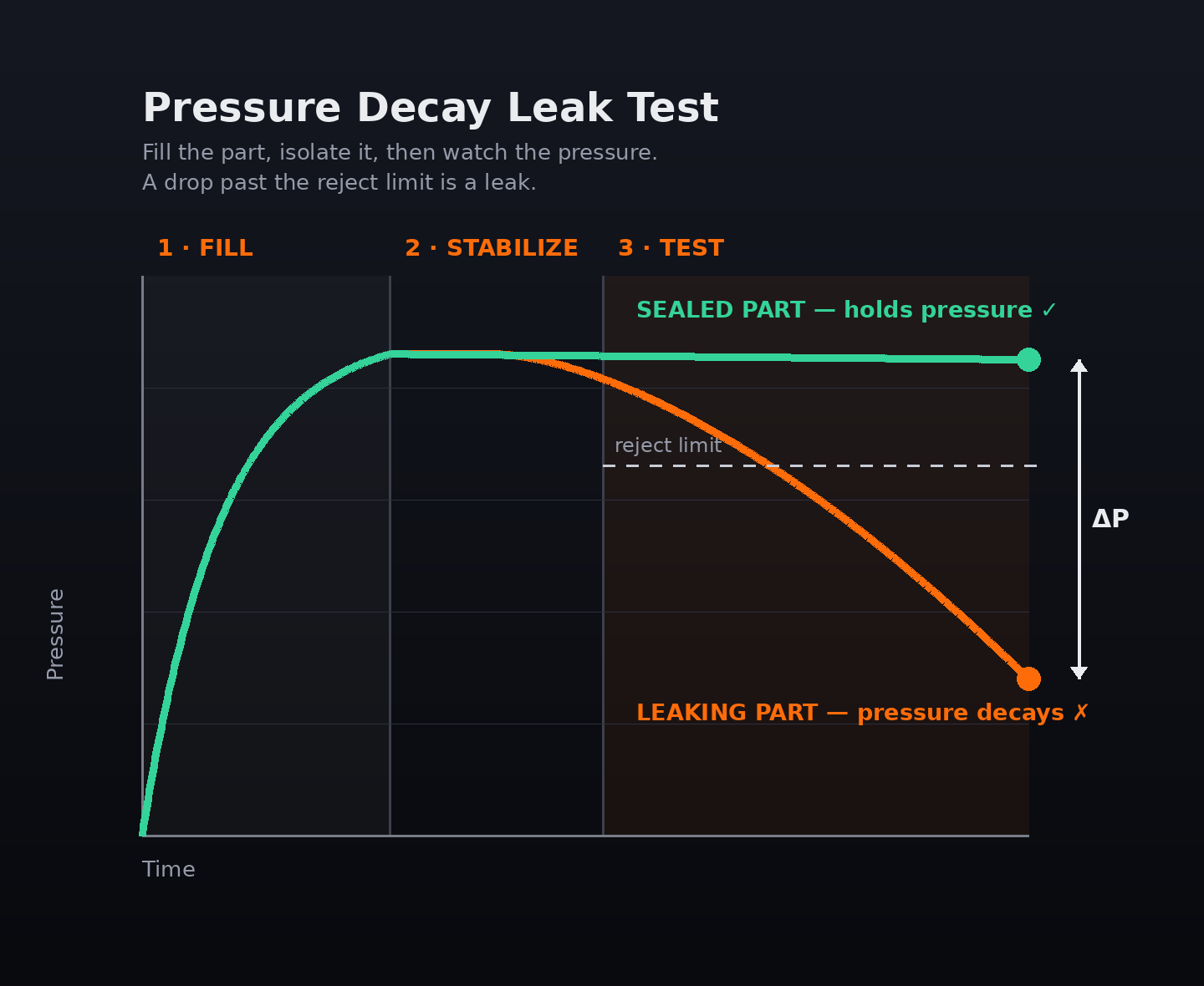
A pressure-decay test pressurizes a sealed part, isolates the air source, and measures pressure drop over a defined interval. Vacuum decay reverses the condition: it evacuates the sealed volume and watches for pressure movement toward atmosphere. Both methods require a controlled connection and a repeatable fixture.
For a cold plate, the measured volume is not only the fluid passage. It includes adapters, hoses, manifolds and fixture cavities connected during the test. The fixture design guide treats the fixture as part of the measurement chain because its seals and added volume affect the result. This is especially important where a cold plate has multiple inlets, outlets or temporary port closures.
A pressure-decay result is a pass/fail response from the complete test circuit. It does not identify a physical leak location. That distinction is useful on a line: a fast air test can separate conforming assemblies, while a second diagnostic operation can locate a seam, fitting or port that needs investigation.
Why decay resolution changes with volume, temperature and time
The leak-rate calculator expresses the settled pressure-decay relationship as Qstd = ΔP × V ÷ (Pstd × Δt). Holding a leak rate constant, a larger enclosed volume produces a smaller measured pressure change over a fixed time. Holding volume constant, a longer measurement interval produces more pressure change. Those are measurement consequences, not universal cycle-time rules.
Direct-to-chip hardware can have a relatively small cold-plate passage, a larger plate-plus-fixture volume, or an assembled loop containing hoses and manifold branches. Each configuration changes V. Adding a long hose, oversized adapter or fixture cavity can therefore reduce the pressure signal available in the same test window. The calculator is a planning tool: enter the actual settled volume, pressure change and test time, then validate the station on representative parts.
The formula also assumes an isothermal interval. In production, fill changes gas temperature; flexible material can stretch, seals can seat, and the part and fixture can equilibrate. The pressure-decay method page consequently separates fill, stabilization, test and vent. If measurement starts while those non-leak effects are still changing pressure, the station can see an apparent leak or hide a small signal. Reducing stabilization to force a short cycle is therefore a measurement trade-off that must be evaluated with the production configuration.
Vacuum decay has the same discipline: evacuate, allow the connected volume to settle, measure, then vent. It can be a suitable air-based peer option when negative pressure fits the part and process. It still observes a pressure response from the connected volume and it still does not pinpoint a leak site.
Fill, stabilize, test and vent
When trace gas becomes the next measurement
Trace-gas testing measures an escaping identifiable gas rather than inferring a leak from pressure change. The trace-gas guide describes sniffing for localizing a leak, accumulation for measuring gas collected around a part, and hard vacuum for the smallest leak-rate reach. The selected method, gas handling and fixture must be considered together.
For a cold plate whose production screen is comfortably resolved by pressure or vacuum decay, trace gas may be reserved for failed-unit diagnosis. When the documented reject limit cannot be discriminated from volume, temperature and time effects in the available air-test window, trace gas can instead be the required confirmation stage. The conclusion is not that trace gas always wins; it is that the evidence must match the requirement.
A two-stage program is normal for cold plates: first make a dry, repeatable gross-to-moderate leak decision with air; then apply a trace-gas sequence where fine-leak sensitivity or localization is required. The first stage protects throughput and catches fixture or assembly issues early. The second stage gives the quality team a more specific signal when the product requirement or failure response calls for it.
Gas choice: helium and hydrogen forming gas
Helium is inert, non-toxic and non-flammable, with low atmospheric background. The trace-gas guide positions it for the smallest reject limits and methods that need helium detection; it also notes that pricing and availability can be volatile, and high-volume users may consider recovery.
Hydrogen forming gas is 5% hydrogen and 95% nitrogen. The same guide describes it as non-flammable, inexpensive and widely available, and positions it as a lower-operating-cost option for sensitive sniffing. Its selection still depends on the detector, ventilation and production environment. Neither gas is a shortcut around a documented acceptance requirement or a controlled station sequence.
Use the gas and detection method together. Sniffing requires physical access to scan the suspected areas. Accumulation requires a controlled collection volume around the part. Hard vacuum follows a different test setup and is used where the smallest leak-rate reach is necessary. Review those choices beside the actual part geometry, fixture and failure-handling plan.
Direct-to-chip selection table
| Part type | Connected volume | Target leak class | Cycle-time context | Recommended method or sequence |
|---|---|---|---|---|
| Single cold plate with accessible ports | Small, controlled fixture volume | Gross to moderate | Production screen | Pressure decay or vacuum decay after representative-part validation |
| Cold plate with added adapters or loop hardware | Volume grows with tooling and connected passages | Moderate; signal must be resolved | Short window under review | Minimize fixture volume; evaluate decay with the calculator; add trace-gas confirmation if needed |
| Cold plate requiring fine-leak evidence | Any volume | Fine | Production plus diagnostic capability | Air screen followed by helium or forming-gas trace test |
| CDU branch or assembled coolant loop | Large or variable connected volume | Gross screen plus fine-leak requirement | Cycle must include stabilization | Stage 1 air test; Stage 2 trace gas by sniffing, accumulation or hard vacuum as the requirement dictates |
| Failed cold plate or fitting | Controlled test boundary | Leak location required | Off-line diagnosis | Trace-gas sniffing after an air-test failure |
| Sealed component suited to evacuation | Controlled volume | Pressure evidence under vacuum | Validated production cycle | Vacuum decay; use trace gas when finer evidence or localization is required |
Build a defensible production sequence
Document the part revision, all connected volumes, permitted pressure or vacuum condition, stabilization and measurement windows, fixture seals, acceptance logic and failed-unit path. The air-test stage is not merely a setpoint: it is fill, stabilization, test and vent performed on the actual part-fixture system.
A trace-gas follow-up should also be explicit. State whether the goal is a location, a collected signal or hard-vacuum sensitivity; state the gas; define the accessible scan path or collection boundary; and record the result with the part and fixture revision. This makes the production result and diagnostic result comparable without pretending they are the same measurement.
Use the leak test method chooser to structure the initial review of access, volume, reject limit, cycle time and required evidence. Validate the selected combination with representative hardware before release.
Measurement boundaries worth reviewing
A cold plate can pass a component-level test and still need an incoming or assembly check after it is connected into a larger system. The later test may include different hoses, QDs, manifold branches and fixture seals, so it is a different measurement boundary. Record that boundary instead of assuming a component limit transfers unchanged.
If a test result shifts, isolate the station before assigning the cause to the part. Check fixture seals, fittings, hoses, port closure and part seating; confirm the programmed stages; then compare environmental and material conditions. This troubleshooting discipline helps separate an internal part leak from a test-circuit change.
Direct-to-chip method selection FAQ
Why can a larger cooling loop be harder to test by pressure decay?
For a fixed leak and test interval, a larger connected volume produces a smaller pressure change. Added fixture cavities, hoses and adapters therefore need to be included in the measurement review.
Does vacuum decay avoid stabilization?
No. Vacuum decay also needs an evacuation, stabilization, measurement and vent sequence. Materials and the connected volume still need to reach a controlled condition before measurement.
When should a cold plate use trace gas?
Use trace gas when the documented requirement needs finer evidence than the available air-test window supports, or when a failed part needs leak localization. Validate the complete station and selected method.
Is hydrogen forming gas the same as pure hydrogen?
No. The trace-gas guide describes forming gas as 5% hydrogen and 95% nitrogen. Select it with the detector and production-environment requirements in mind.
Does trace gas replace an air test on every cold plate?
No. Air and trace-gas methods are peer choices. A two-stage air screen followed by trace-gas confirmation or diagnosis is a normal production approach for cold plates.