
Engineering Guide
Leak Test Fixture Design: An Engineering Guide
A fixture is part of the measurement chain: it holds the part, creates the intended seal and presents a controlled test volume to the leak tester.
Good fixture design makes the measurement repeatable before a test program ever decides pass or fail. It begins with the part, ports, material behavior and production sequence—not a generic clamp.
Request a fixture reviewWhat a fixture does in the measurement chain
A leak tester measures a response from a connected part and test circuit. The fixture is the controlled interface between them. It locates the part, seals the openings that are not under test, makes the intended connection, and limits uncontrolled air volume. That is why a fixture can change the quality of the measurement even when the same instrument and program are retained.
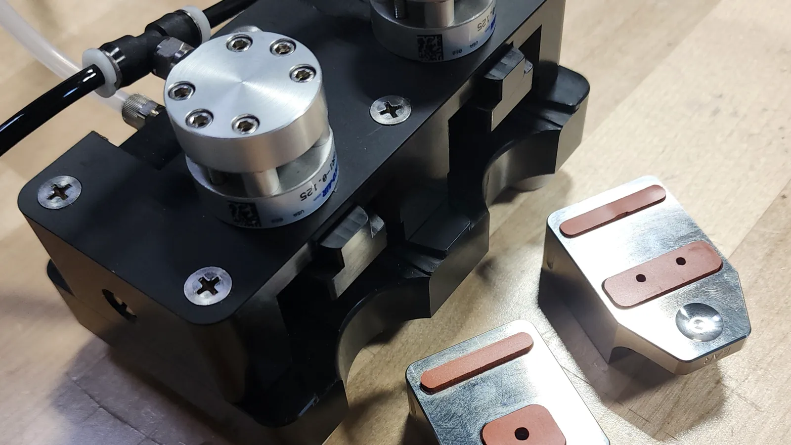
For a simple ported part, a standard fitting may be enough. Complex geometry, several openings, finished enclosures without a service port, or an automated cell often need a purpose-built sealing fixture or chamber. Zaxis designs and machines custom fixtures with the selected tester so the complete system can be evaluated together.
Choose a sealing strategy before choosing hardware
List every opening, mating surface and feature that can influence the test. O-rings and gaskets can make repeatable seals when their material, groove, surface condition and compression fit the part. Port seals must avoid damaging threads, bores or delicate connectors. A clamp must apply enough controlled force to maintain the seal without distorting a flexible housing or changing the product condition being measured.
Part variation matters. Casting texture, molded features, tolerance stack-up, surface contamination and component assembly can change how a seal lands. Design the nest and locating features so the part arrives in a consistent position. If an operator or robot loads the fixture, make the correct orientation and full seating observable rather than relying on force alone.
Minimize internal and test volume
Every hose, adapter, cavity and oversized chamber adds volume to the circuit. With pressure or vacuum decay, that added volume affects how a given leak changes the measured pressure over time. A compact route between tester and part, correctly sized fittings, and a close-fitting chamber make the response easier to interpret. Zaxis’s drawer-fixture guidance similarly calls for very little volume around a chamber-tested part.
Do not reduce volume by creating a difficult-to-clean or difficult-to-service fixture. Instead, document what volume belongs to the product and what volume belongs to the test system, then evaluate the assembled station with representative parts.
Stabilization, temperature and handling effects
Compression, fill or evacuation can change gas temperature; flexible parts can relax; and an operator’s handling can add heat. A stabilization interval lets these effects settle before the measurement window. The right interval is established with the actual part, fixture, gas path and production environment—not assumed from a tester setting alone.
Keep the test location and loading process consistent. Separate a thermal or handling change from a leak indication by reviewing repeat tests, fixture condition and the complete timing sequence. Zaxis’s guidance on external influences and test volume is useful background when an otherwise capable station produces false failures.
Multi-port and multi-cavity parts
For manifolds, assemblies and multi-cavity products, make the test boundary explicit. The fixture may need to close several ports, connect selected cavities or sequence tests. Label each connection, prevent cross-connection, and decide whether all cavities are evaluated together or independently. A failure should lead to an actionable next step rather than an ambiguous result from an unknown combined volume.
When a finished enclosure has no direct port, a chamber can test the space around it. Chamber geometry, door or drawer seals and the unused volume surrounding the product become part of the system design.
Separate a fixture leak from a part leak
Start troubleshooting by testing the fixture, connections and seal surfaces independently from the product. Inspect O-rings, fittings, clamp travel and any quick-change nest. Then use a calibrated leak or master leak to verify that the station responds to a known reference under the programmed sequence. This check is not a substitute for the manufacturer’s validation; it is practical evidence that the fixture and method are behaving as expected.
Keep a record of the part revision, fixture revision, program, reference leak and maintenance action. It helps distinguish a product change from a worn seal, loose connection or timing change.
Plan the automation interface
An automated station may combine pneumatic clamps, valves, guarding, part-present sensing, operator acknowledgement and PLC signals. Define which device owns the sequence, what confirms a fully seated part, and what happens after pass, fail or fault. Zaxis connectivity options should be confirmed for the specific platform and line; current guidance includes 24 VDC I/O and network or serial options on compatible systems.
Design access for seal replacement, cleaning, changeover and fault recovery. Automation that cannot reveal a missing part, a partial clamp or a blocked port can hide the source of test variation.
Match the fixture to the method
Pressure decay uses a sealed positive-pressure test volume; vacuum decay observes movement back toward atmospheric pressure after evacuation. A chamber fixture can make an external test possible for a finished product without a port. Trace gas uses a measurable tracer when the application calls for that method. These are peer choices: fixture design follows the documented requirement, part access and production evidence needed.
Document the test boundary
State which volume and which surfaces are intentionally tested. Record the part revision, all closed ports, the fixture cavity and any adapters between tester and product. This prevents an engineering team from interpreting a fixture change as a material or assembly change. It also provides a practical basis for comparing a first article, a maintenance check and a production result.
Where a test sequence includes several stages, retain the order: load, clamp, connect, fill or evacuate, stabilize, measure, vent and release. The sequence gives technicians a way to ask where variation entered the system rather than merely whether the final result crossed a limit.
RFQ intake checklist
Bring the following information to a fixture review. Zaxis engineers custom fixtures with the selected leak tester; a drawing, representative part and test requirement make the discussion more productive.
| Input | What to provide |
|---|---|
| Part geometry | Drawing, datum features, tolerance concerns and loading orientation |
| Materials | Housing, seal-contact and temperature-sensitive materials |
| Ports | Quantity, size, threads, bores and openings to close |
| Test pressure | Target pressure or vacuum and allowable operating condition |
| Leak limit & units | Documented acceptance limit and measurement units |
| Cycle time | Load, settle, measure, vent and unload target |
| Environment | Temperature, contamination, cleaning and guarding constraints |
| Automation interface | PLC I/O, safety sequence, part presentation and traceability needs |
| Volumes | Known part volume and restrictions on fixture, hose or chamber volume |
Build verification into the fixture plan
A fixture drawing is only one control. Define how operators confirm the correct nest, how maintenance confirms seal condition, and how the station proves a known response after a change. A part-present sensor can prevent a cycle with an empty nest; a clamp-position signal can show whether the intended sequence occurred; and a documented reference check can reveal a changed pneumatic path before it is mistaken for product variation.
Consider the service path at the same time as the loading path. Seals, adapters and high-contact surfaces should be accessible without changing critical locations or reconnecting tubing in an uncontrolled way. For families of parts, use keyed nests and program selection that prevents a fixture-program mismatch. Keep the production record linked to the fixture and part revision so later engineering review has context.
Finally, evaluate repeatability with representative good parts, expected part variation and the actual station sequence. A test can look stable on a rigid laboratory surrogate yet respond differently after an operator, robot, warm part or adjacent process is introduced. Review those conditions before setting a production limit.
Fixture design FAQ
What is a leak-test fixture?
A leak-test fixture holds, seals and connects a part so the selected method can measure the intended test volume rather than uncontrolled openings or handling variation.
Why is fixture volume important?
Added fixture, hose and chamber volume changes the pressure response. A compact, repeatable test circuit improves the usefulness of a pressure or vacuum measurement.
How do I tell a fixture leak from a part leak?
Verify the fixture and its connections separately, then use a calibrated or master leak to confirm that the programmed method responds as expected.
Can one fixture test multiple ports?
Yes. A fixture can close multiple ports and sequence connections, but each seal, cavity and part presentation must be designed so it can be verified independently.
Can a fixture be integrated with automation?
Yes. Pneumatic clamping, part-present sensing and defined PLC I/O can be designed around the selected tester and cell process.
Which test methods need a fixture?
Pressure decay, vacuum decay, chamber testing and trace-gas testing can all require purpose-built sealing and handling. The right fixture follows the part, method and acceptance requirement.