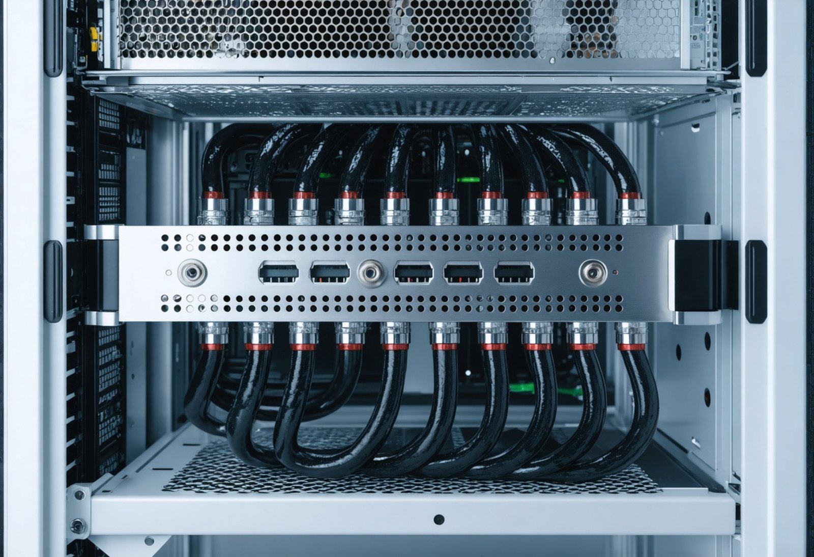
Rear of a liquid-cooled server chassis showing blind-mate manifold with stainless quick-disconnect ports and braided coolant hoses

Industry Solutions

Data Center Liquid Cooling Leak Testing

Leak testing for direct-to-chip liquid-cooling hardware in AI data-center production.

Cold plates, rack manifolds, quick-disconnects, hoses and coolant distribution units bring liquid close to high-value computing hardware. Production teams use a controlled, dry leak test to verify the sealed boundary before assembly.

Air leak testing and trace-gas leak testing are peer options. Pressure decay, vacuum decay and mass flow suit gross-leak and production screening; helium or hydrogen trace-gas methods provide a measurable tracer when the required target or localization task calls for it.

Request for QuoteRequest a Demo

What gets tested

Direct-to-chip liquid cooling puts a coolant circuit next to GPUs, CPUs and memory. Every joint in that circuit — brazed cold-plate passages, manifold branches, quick-disconnect seal faces, hose crimps and CDU connections — is a potential leak path, and a slow leak in a running rack is an expensive field failure.

Production teams therefore test the component where it is made and again when it is integrated into a rack or loop. Each part needs a method, fixture and acceptance target appropriate to its volume, access and purpose rather than one generic recipe for the whole assembly.

•Cold plates•Cold-plate loops and tubing•Rack manifolds•Quick-disconnects•Hoses•Coolant distribution units (CDUs)•Brazed heat exchangers•Pumps•Immersion-tank fittings

Methods used

Choosing the method

Choose a method around the connected volume, temperature stability, required decision and whether the station must localize a leak.

Air: pressure decay, vacuum decay and mass flow

Pressure or vacuum decay measures a controlled change after a sealed part is isolated. Mass flow measures gas through a connected path. These air methods are dry, repeatable production tools when the fixture, settle time and acceptance target are defined.

Compare air leak-test methods →
Trace gas: sniffing, accumulation and hard vacuum

Helium or hydrogen forming gas gives the detector an identifiable tracer. Sniffing can localize accessible seams, accumulation measures tracer collected around a part, and hard vacuum addresses the smallest leak paths.

Explore trace-gas methods →

Test methods by component

Method selection and acceptance criteria are part-specific. The table identifies common starting points; validate the fixture, sequence and target for the production part.

ComponentRecommended methodWhyZaxis product
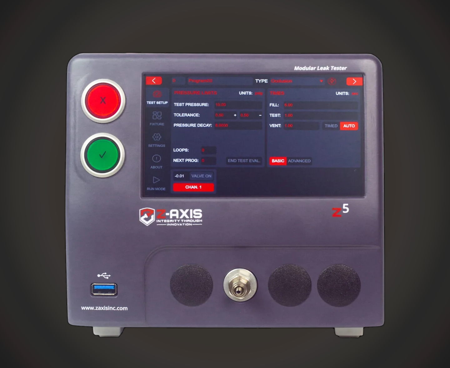
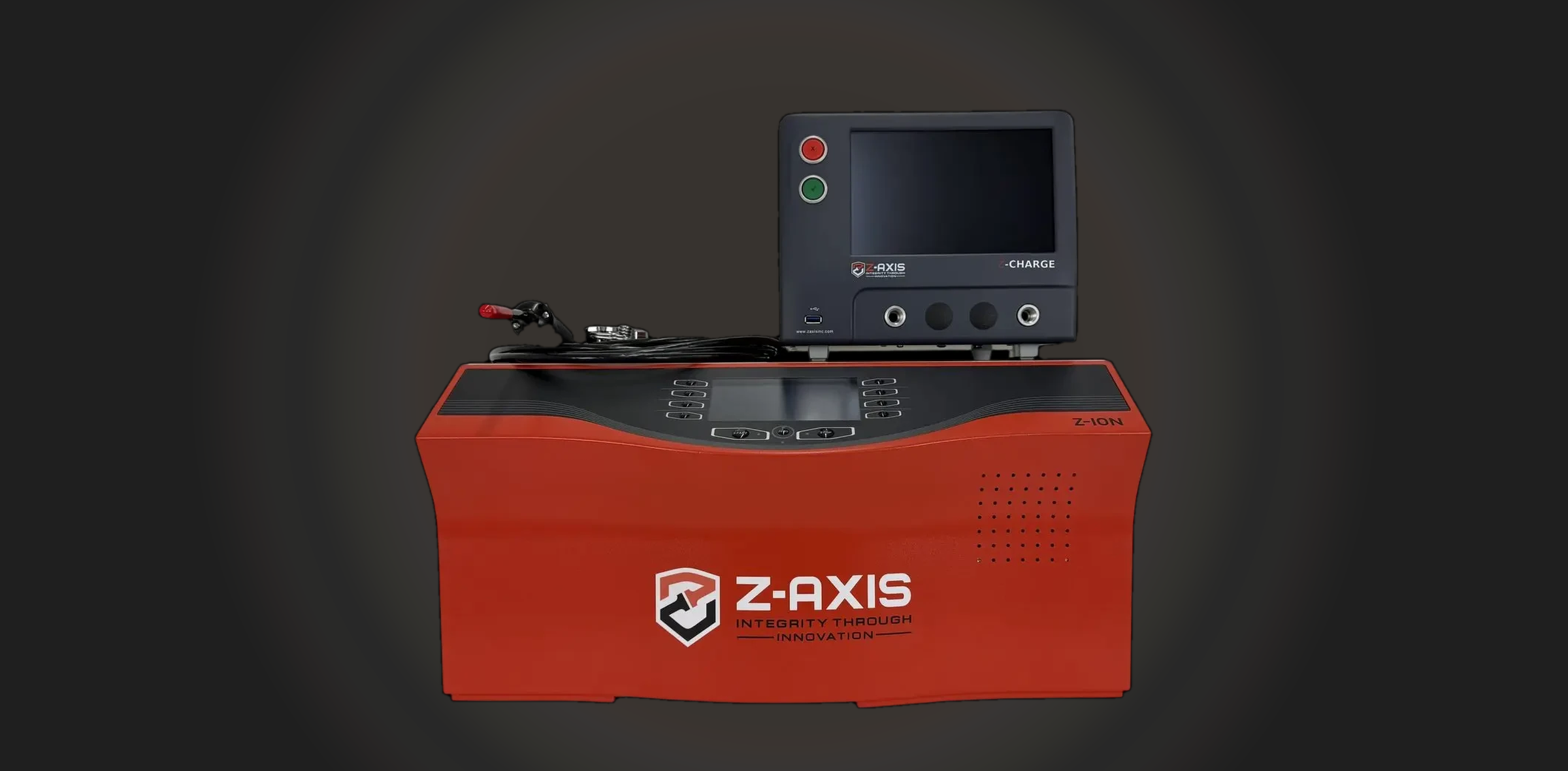
Cold plate or cold-plate loopPressure or vacuum decay screen; helium or hydrogen sniff or accumulation for fine leaksBrazed passages and port seals need a gross screen first; a tracer method resolves the fine-leak target without the volume and temperature limits of a decay test.Z5 or Z8 air testers; Z-Charge + Z-Ion for trace gas
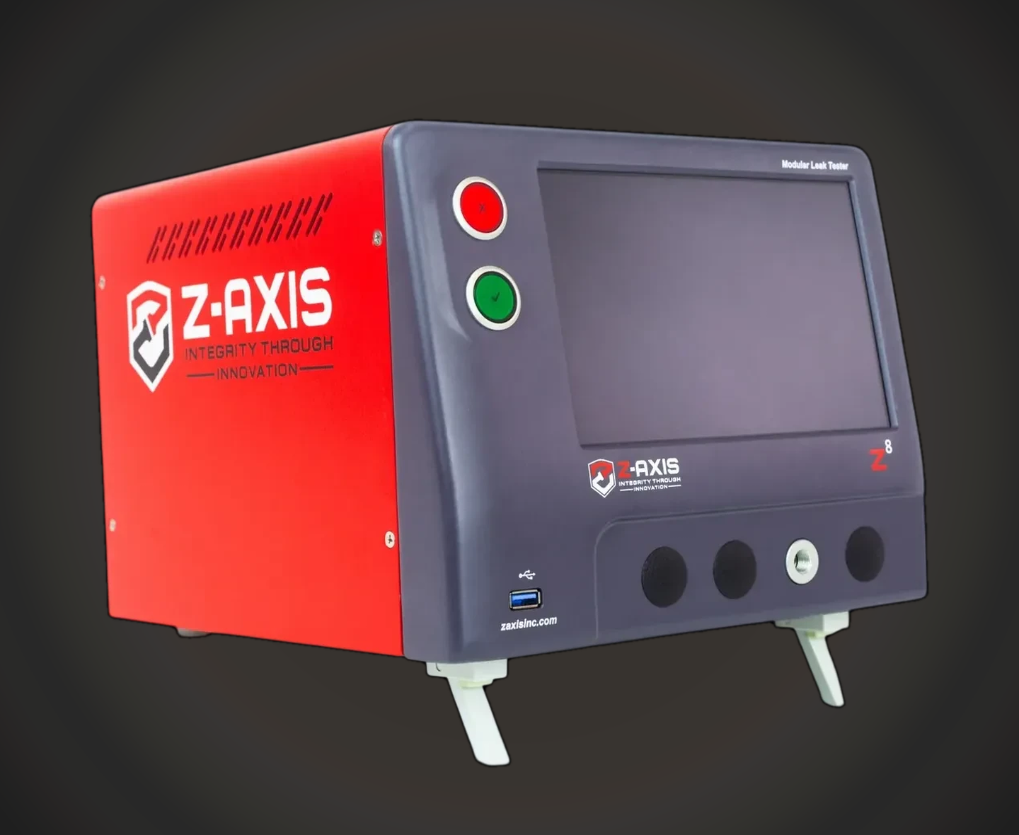
Rack manifold or CDUPressure decay or mass flow; helium or hydrogen sniff to localizeMany ports and a large connected volume call for a sealed-port fixture, stabilization time and a sniff probe to find which joint failed.Z8 multi-port air tester; Z-Charge + Z-Ion
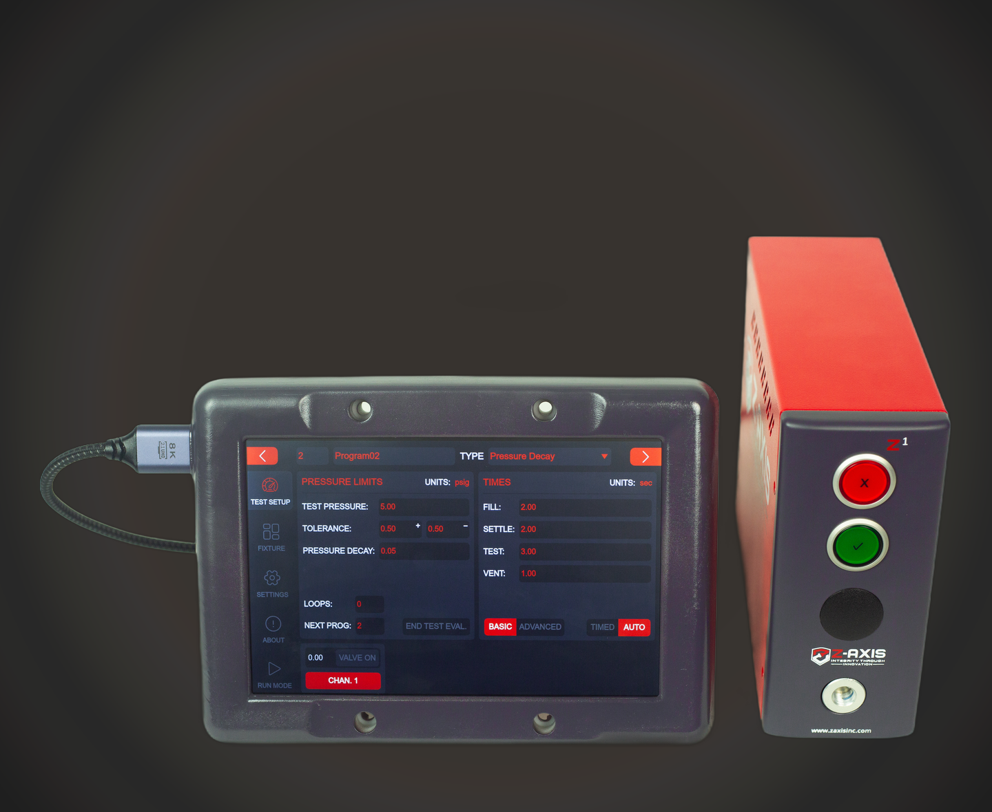
Quick-disconnect or immersion-tank fittingPressure or vacuum decay, coupled and uncoupled; helium or hydrogen sniff for seal facesSmall volume gives a fast decay test; the seal face is the failure point and sniffing locates it without masking access.Z1 or Z5 air testers; Z-Charge + Z-Ion
Hose, pump or brazed heat exchangerPressure or vacuum decay; helium or hydrogen accumulation or hard vacuum for the tightest targetsFlexible or multi-circuit parts add compliance and volume; accumulation and hard vacuum measure total leakage when a decay test cannot reach the target.Z5 or Z8 air testers; Z-Charge + Z-Ion

Standards and guidance context

ASHRAE Technical Committee 9.9 provides thermal guidance for data-processing environments, including liquid-cooling context. The manufacturer defines the acceptance criteria and validation plan for its product and process.

✓ASHRAE TC 9.9: thermal guidance context

In depth: liquid-cooling hardware

Production sequence and fixturing

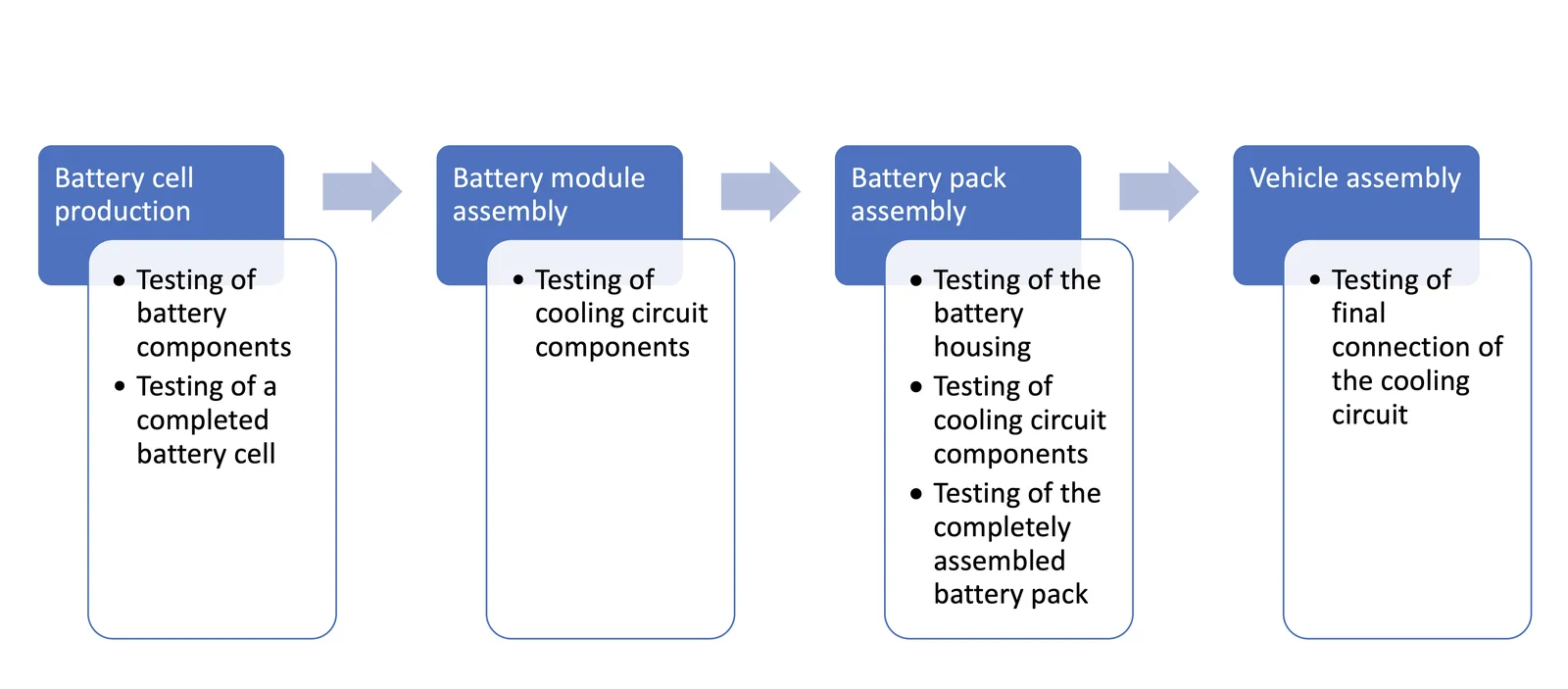
A component maker can screen a cold plate, hose or manifold before shipment, then a rack integrator can test incoming hardware or a completed fluid path. This two-stage approach keeps a part-level result separate from a later assembly verification.

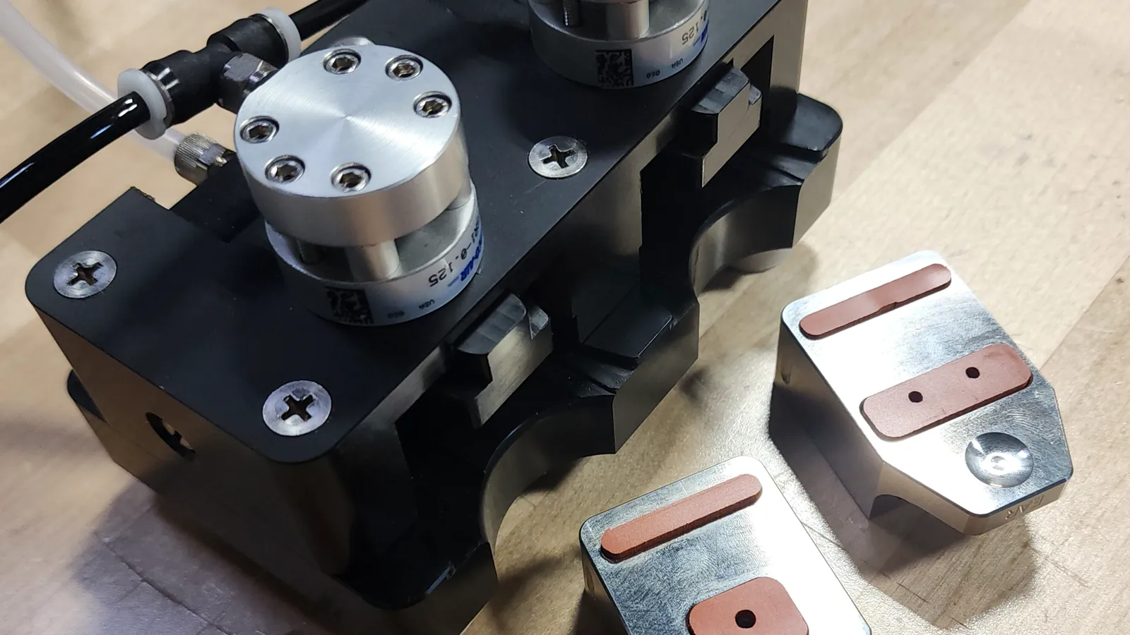
Fixture design controls where the test volume begins and ends. Seal unused ports, minimize unnecessary adapters, allow stabilization, and preserve access when a trace-gas sniff is required.

Zaxis tester connected to a custom leak-test fixture

Applications in this industry

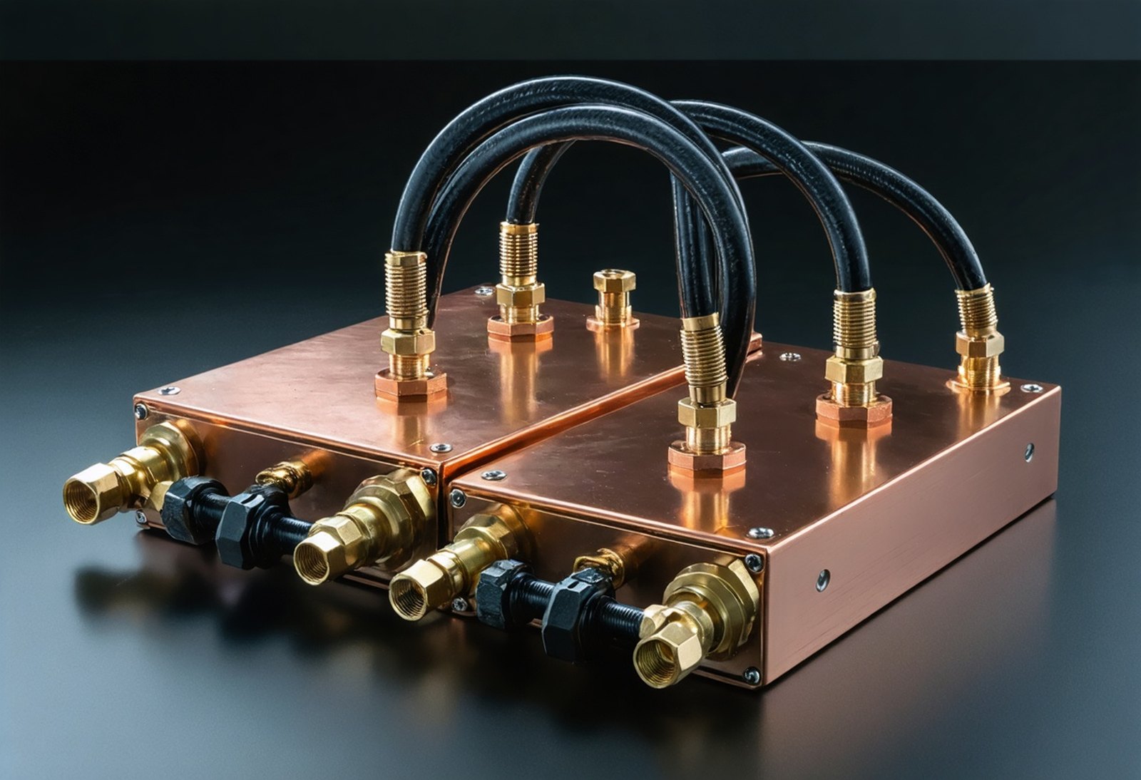
Two copper cold plates joined by coolant hoses and quick-disconnects

Cold plates and CDU circuits

Connected cooling paths can be tested with an air or trace-gas sequence selected around volume, seals and the required production decision.

Data Center Liquid Cooling Leak Testing FAQ

Why test liquid-cooling components twice?

A component-level test can identify a defect before shipment; an incoming or assembled-rack test evaluates the later connections and assembly boundary.

Which methods are peer options?

Pressure decay, vacuum decay and mass flow are air methods; helium or hydrogen trace-gas testing can use sniffing, accumulation or hard vacuum.

Can pressure decay test a cold plate?

A sealed cold plate can use pressure decay when the fixture, volume, stabilization and target are defined.

When does trace gas help?

Trace gas provides a measurable tracer when the target calls for fine-leak detection or a station needs to localize an accessible leak.

What affects cycle time?

Connected volume, part and gas temperature, stabilization time, fixture volume and the selected method all affect a production sequence.

Are standards acceptance limits?

Standards and guidance identify scope; the manufacturer establishes the acceptance target and validation plan.

Plan a liquid-cooling leak-test cell

Request for Quote
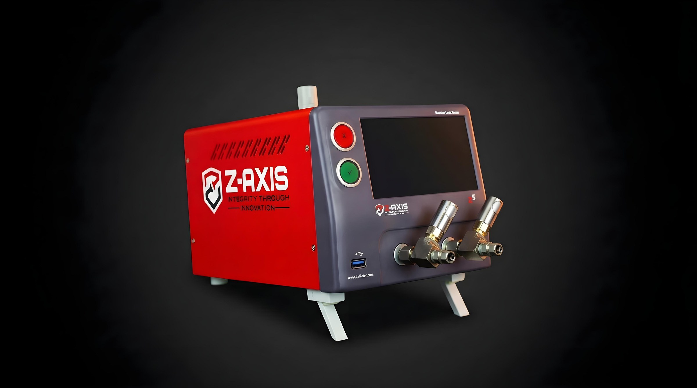
Zaxis Z8 leak tester