
Automation integration
Leak Tester PLC & Automation Integration Guide
Plan an air leak-test station around the published interface, fixture and workflow.
Request a QuoteInterface matrix
This matrix is an integration starting point, not a protocol promise beyond the linked product pages. Confirm the exact configured tester and station requirement with Zaxis.
| Model | Published interfaces | Published station note |
|---|---|---|
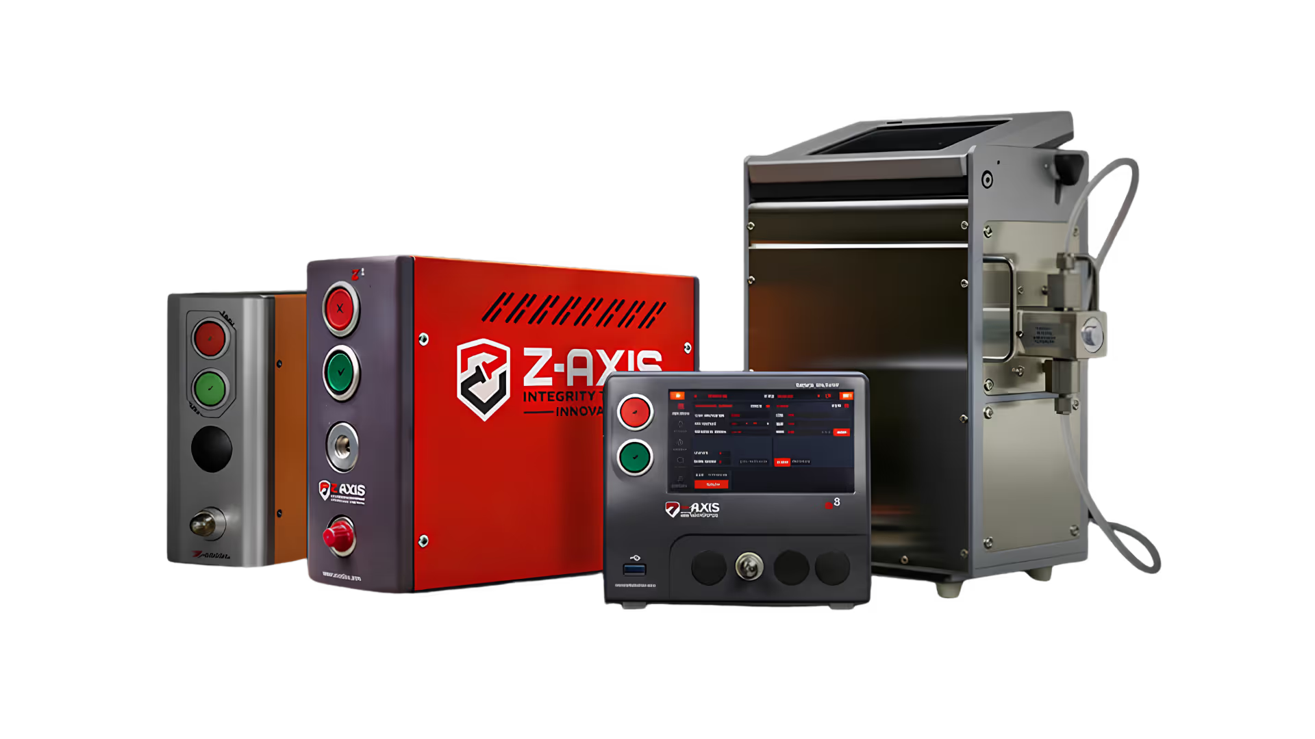
| Z1 | OPC UA, USB, EtherNet/IP, TCP/IP, 24 VDC I/O | Optional pneumatic valves; optional onboard result storage |
| Z5 | OPC UA, USB, EtherNet/IP, TCP/IP, 24 VDC I/O | Start, pass, fail and busy signals; up to four pneumatic valves |
| Z5L | USB, TCP/IP | Optional onboard result storage and statistics |
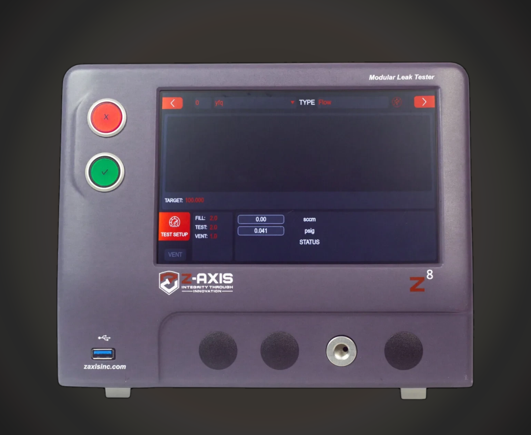
| Z8 | OPC UA, USB, EtherNet/IP, TCP/IP, RS232 datalogging output, RS485, 24 VDC I/O | Optional onboard result storage |
| Z8N | RS232, I/O, Ethernet TCP/IP, EtherNet/IP | Up to 100 stored programs |
| VM3 | USB, RS232, Ethernet TCP/IP; optional EtherNet/IP | Up to 100 stored programs |
A PLC-controlled station
A practical station has a PLC or cell controller, a Zaxis tester, a fixture and part-handling equipment. The controller selects the appropriate stored program where supported, commands the fixture sequence, starts the test, receives the configured result and releases or routes the part. On the Z5, the product page publishes 24 VDC digital I/O for start, pass, fail and busy signals. Treat the signal map and fault handling as station-specific engineering work.
For result traceability, keep the station identifier, part identifier where the cell provides it, selected program and tester result together in the line record. Z1, Z5, Z5L and Z8 product pages describe optional onboard result storage with statistics; verify configuration and retention needs during design.
Fixture actuation and sequence
The Z1 page publishes optional pneumatic valves for tooling motions and fixtures. The Z5 page publishes up to four optional pneumatic valves for fixture clamps and tooling motions. Pair those options with the fixture design guide; testers and fixtures should be specified together.
Text architecture: PLC/cell controller → configured network or I/O → Zaxis tester → fixture valves and sealed part; tester result → PLC → station record/MES path selected by the integrator. This is an architecture description, not a claim that every model provides every connection.
Multi-station planning
The air-leak-testers hub describes cascaded Z1 units for synchronous multi-channel cells. Use one tester per required independent channel and make the PLC sequence explicit. For other platforms, compare ports, methods and configuration with the leak tester comparison.
Questions to resolve with an integrator
Document the part and fixture, cycle target, selected method, signal map, network option, data owner, program control, reject handling, service access and recovery behavior. The connectivity page and configuration options provide the published starting points.
Data, programs and handoff
Choose the program-management boundary early. A tester can retain published stored programs while the PLC determines which part is present and which sequence is authorized. Capture a configuration revision and route the station through a controlled change process when parameters move between engineering and production.
Decide which system is the record of truth. Tester-level result storage can support review, while a PLC, line database or MES may own the production record. Map result status, time, program, station and part identifier only where the cell can supply them. Data architecture is an integrator decision, not a generic feature claim.
Design abnormal-state behavior too: no part, incomplete clamp, loss of communication, failed test, operator reset and service mode. A clear state model makes I/O and network integration easier to validate than a pass/fail signal alone. Keep pneumatic safety and machine guarding under the station designer’s responsibility.
Before commissioning, exercise the full route with representative parts, result handling, rework rules and recovery behavior. Confirm model options against the individual product page because interfaces and optional features vary by model and configuration.
Integration review checklist
Prepare: selected tester model and options; method and pressure configuration; fixture drawing and pneumatic sequence; PLC manufacturer and target interface; I/O list; program-selection approach; data owner and retention; part identification; reject path; cycle requirement; service access; and acceptance plan. This list creates a focused conversation without implying support for a protocol not published for the selected model.
Use the published product pages as the claim source for the matrix above. For details beyond them, request a configuration review and quote rather than carrying a capability assumption into a production design.
Frequently asked questions
Which interfaces does each model support?
The matrix lists only interfaces published on each linked product page.
Can a PLC use discrete signals?
Z5 publishes 24 VDC digital I/O for start, pass, fail and busy signals.
Can results be stored?
Selected active models publish optional onboard result storage and statistics.
Can the tester move a fixture?
Z1 and Z5 publish optional pneumatic valves for fixture and tooling motions.
Can one line use multiple Z1 testers?
The Z1 page describes cascading units for synchronous multi-channel cells.