
Liquid-Cooling Production Guide
Quick-Disconnect & Rack Manifold Leak Testing at Production Rate
Test the intended sealed boundary in its actual state—coupled and uncoupled—while keeping many ports, fixture seals and failure data under control.
Quick-disconnect couplings, blind-mate interfaces, rack manifolds and hoses with crimped ends create production test boundaries with multiple ports and many possible leak paths. The test fixture determines whether the station measures the hardware or its own seals.
Use air methods and trace gas as peer options. A production air screen can make a dry pass/fail decision; trace-gas sniffing can add a location step when a port, crimp, O-ring interface or manifold joint needs investigation.
Define the coupled and uncoupled boundaries
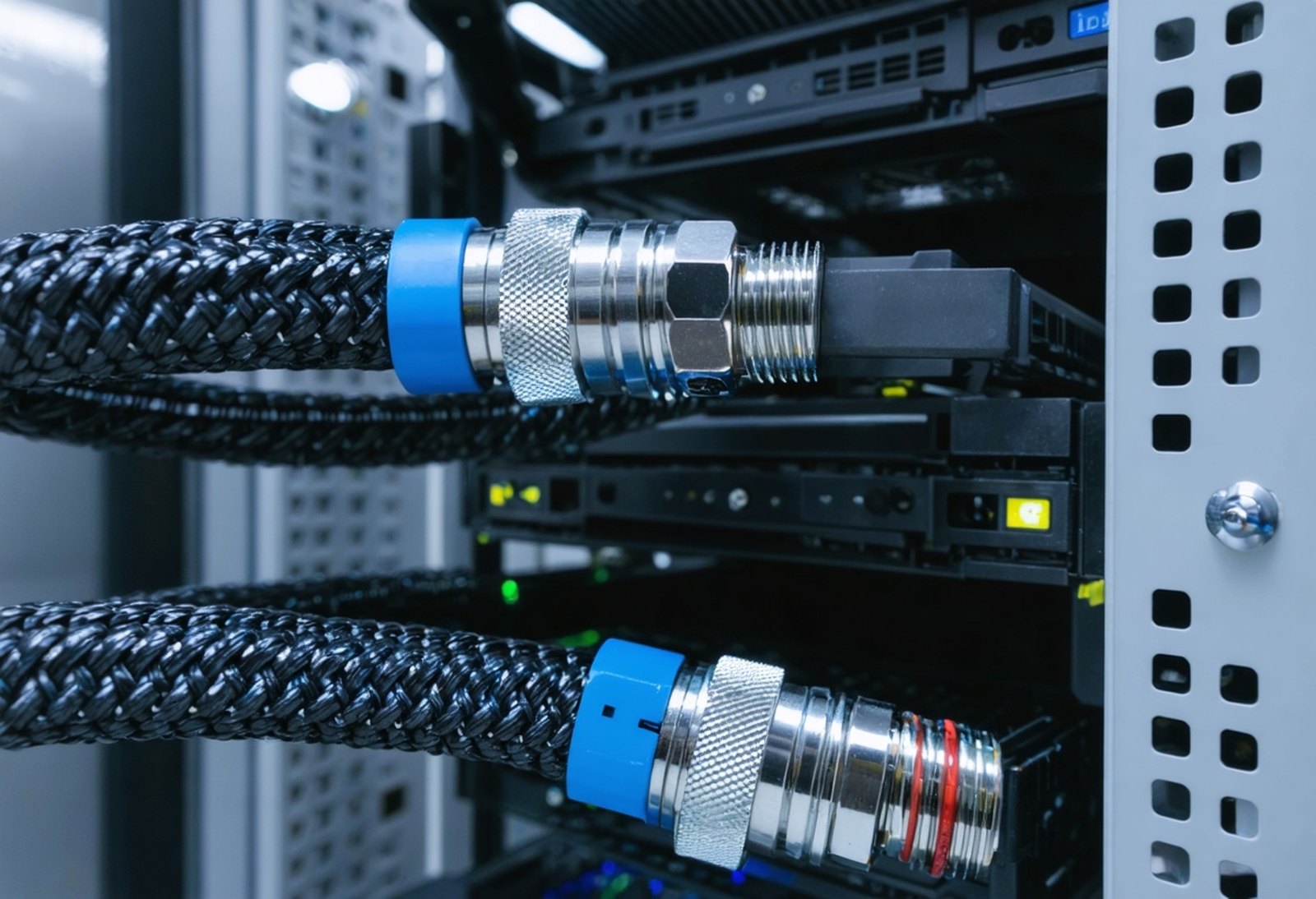
A QD may need testing in both coupled and uncoupled states. In the coupled state, test the mating interface and the intended assembled flow path. In the uncoupled state, test the valve or dry-break closure and any protective cap or temporary closure that represents the product condition. These are different boundaries and may need different fixtures and programs.
Blind-mate hardware adds a further condition: the production fixture must reproduce the intended alignment and engagement without masking a leak or damaging the interface. Record which state was tested, the part revision and the fixture configuration with the result.
For rack manifolds, decide whether a station measures the whole manifold as one connected volume or isolates each branch. A combined result can be suitable for a gross screen; an independent-port strategy can make a failure more diagnosable. The choice depends on the documented requirement and fixture feasibility, not on a generic channel-count claim.
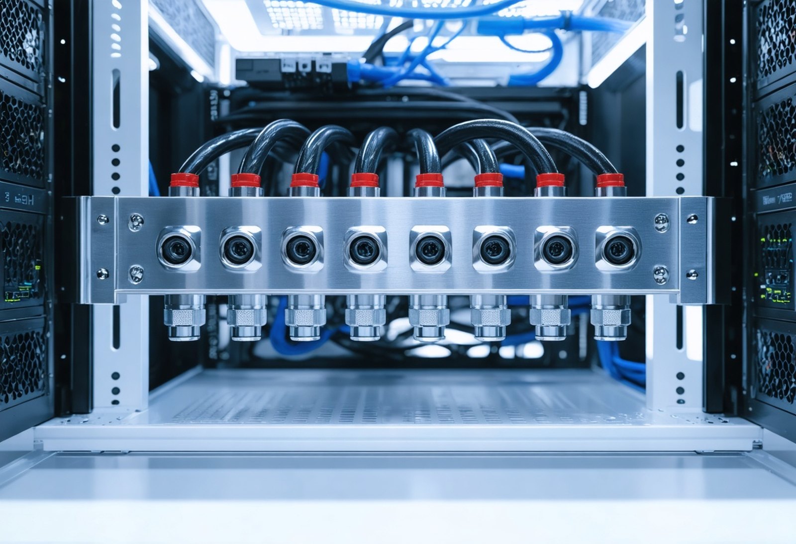
Coupled hoses at the rack manifold
Seal and fixture many ports deliberately
Every uncapped port, temporary plug, hose, adapter and fixture cavity is part of the test circuit. The leak test fixture design guide recommends listing openings and mating surfaces, locating the part consistently, choosing sealing interfaces that do not damage the part, and minimizing uncontrolled volume.
For a manifold, map every branch, return, service port and sensor connection before selecting seals. A fixture may use dedicated port closures, controlled O-ring contacts or a chamber boundary where direct connection is impractical. The fixture needs a way to distinguish its own leakage from the assembly response before a production lot is rejected.
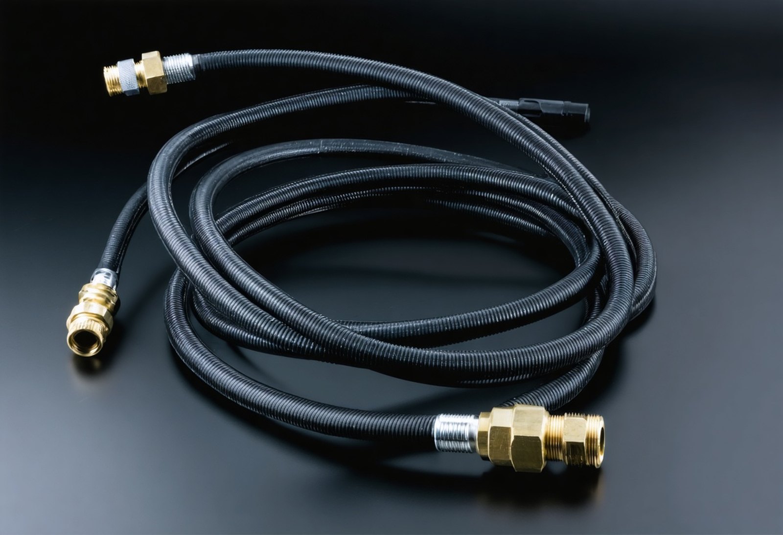
Hoses with crimped ends require the same discipline. Test the hose assembly in the condition the customer will use, with fixture connections that do not substitute for the product’s crimp or end seal. If the fixture must connect through a temporary adapter, include that adapter’s volume and sealing behavior in validation.
Crimped hose assembly with quick-disconnect
Run the production sequence, not a guessed cycle time
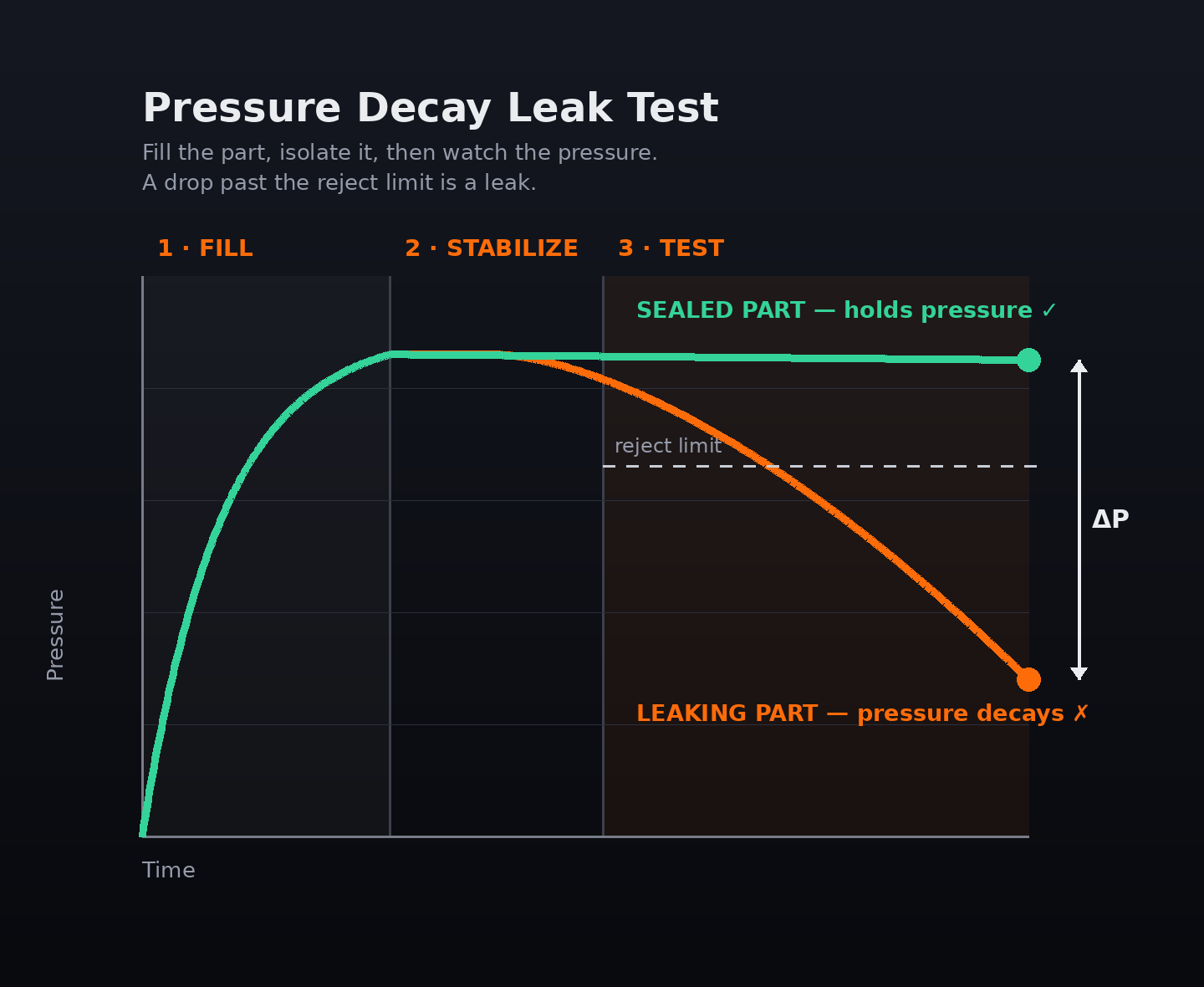
Pressure decay is a sequence of fill, stabilization, test and vent. Fill brings the connected circuit to the programmed condition. Stabilization allows pressure and temperature effects, material motion and seal seating to settle. The test stage measures the isolated response, and vent returns the part or fixture to a disconnectable condition.
Production-rate planning is therefore a phase-by-phase exercise. Measure loading and connection, fill, stabilization, measurement, vent, unloading and data exchange on representative assemblies. Do not assign a universal cycle time to a QD or manifold: internal volume, fixture plumbing, supply, materials, acceptance logic and the failure response all change the result.
The pressure-decay buyer’s guide explains why larger connected volumes generally need more time to produce a useful pressure change from the same leak. Use the leak-rate calculator to examine the actual settled volume, observed pressure change and test time, then validate the recipe with the complete station.
Pressure-decay stages on the station
Choose the method from the evidence required
| Assembly or state | Primary production question | Air-method route | Trace-gas route | Failure response |
|---|---|---|---|---|
| QD, uncoupled | Does the closure hold the specified boundary? | Pressure or vacuum decay with a controlled port closure | Sniff only where a location is needed | Retest controlled setup; then localize closure or seal path |
| QD, coupled or blind-mate | Does the mated interface and path hold? | Pressure decay on the connected assembly | Sniff accessible mating areas after a failed screen | Compare fixture engagement and mating condition |
| Rack manifold, all ports sealed | Does the complete assembly hold? | Pressure or vacuum decay on the defined combined volume | Accumulation or sniffing where fine evidence or location is required | Determine whether combined response needs branch isolation |
| Rack manifold, individual branches | Which branch needs action? | Separate controlled test boundaries where fixture design supports it | Sniff failed branch and joints | Record port identity with result |
| Crimped hose assembly | Do the hose and end connections hold? | Air test with product-representative end connections | Sniff crimp/end area after failure | Inspect fixture connection before assigning the failure |
Use trace gas to localize, not to skip process control
A pressure or vacuum decay result does not identify where gas is leaving or entering the boundary. After a failed production screen, trace-gas sniffing can scan accessible QD bodies, blind-mate interfaces, manifold joints, plugs and hose crimps for an escaping identifiable gas.
The trace-gas guide distinguishes sniffing, accumulation and hard-vacuum methods. Helium suits the smallest reject limits and helium detection methods; hydrogen forming gas is 5% hydrogen and 95% nitrogen and is described there as a lower-operating-cost option for sensitive sniffing. Select the gas, detector, ventilation and scan path together.
A localizing step does not absolve the air-test cell from fixture checks. First verify part seating, port closures, tubing and fixture seals. Then use trace gas to find the product-side location when that added evidence is required.
Automation and data are part of throughput
A production cell needs a controlled handoff among part handling, fixture, tester and record system. The PLC and automation integration guide covers station planning around the published interface, fixture and workflow, including the need to keep the selected program and tester result with the line record.
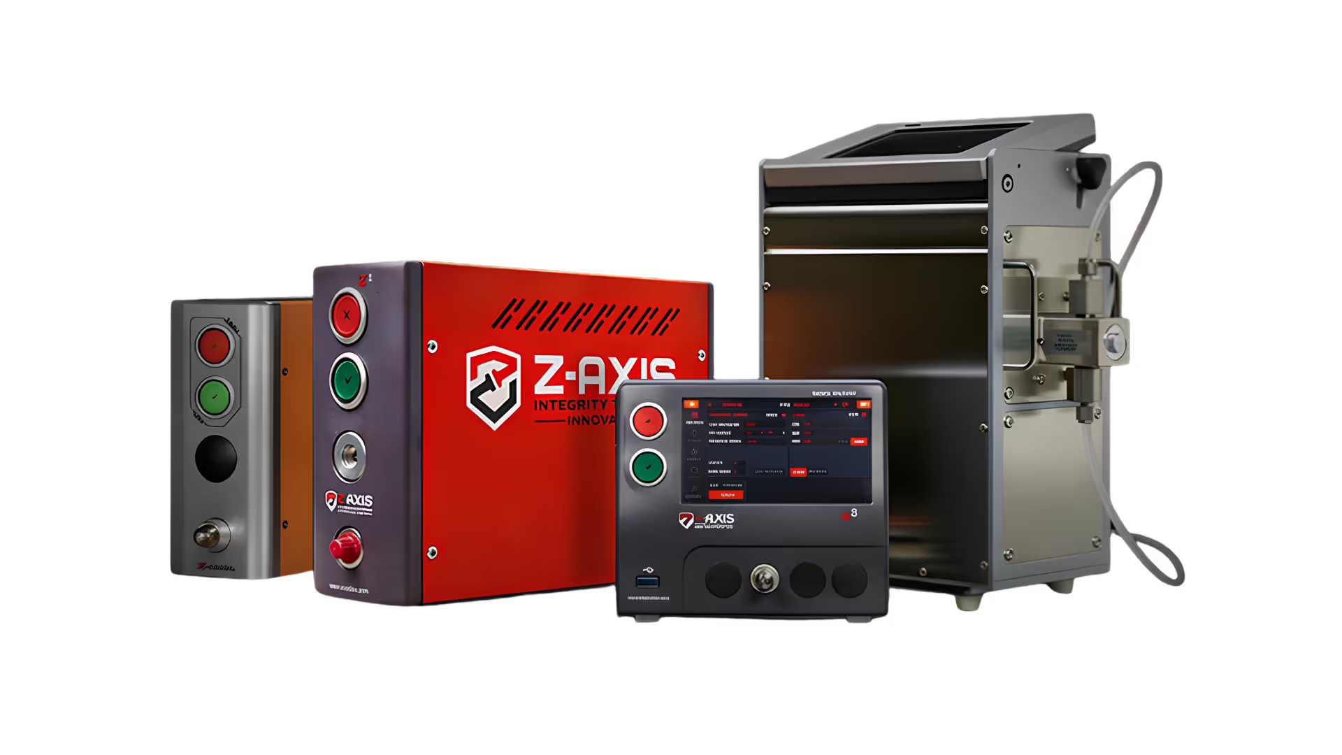
For a many-port fixture, record the assembly identifier, fixture identity, state tested (coupled or uncoupled), selected program, result and any diagnosed port or branch. Where a station tests several ports or several parts at once, the Z5 and Z8 air leak testers support up to four test ports that run concurrently or sequentially, each with its own program parameters and pass/fail result, so a branch or a position can be reported independently. Document the configured channel count and the reporting behavior before release.
Fail handling needs as much design attention as the pass path. Decide whether the line repeats a controlled test, routes the unit to a trace-gas localization station, identifies a branch for repair, or quarantines the assembly. That preserves throughput without quietly changing the evidence used for acceptance.
Production review checklist
Review the exact assembly state, every sealed port, the part and fixture volumes, the program phases, the allowed pressure or vacuum condition, the acceptance logic and the required record. Include known-good and representative variation in the validation plan.
For a QD or blind-mate design, verify that the fixture does not over-constrain alignment or hide the feature under test. For a manifold, verify that a branch closure or cap does not become the dominant signal. For hoses, verify that the fixture connection does not bypass the crimped-end question.
When a result changes, compare the test boundary rather than changing a reject limit by assumption. The repeatable production decision comes from the complete part-fixture-program system.
QD and manifold production-test FAQ
Should a quick disconnect be tested coupled and uncoupled?
When both states are product-relevant, test both states as separate defined boundaries. The coupled test addresses the mated path; the uncoupled test addresses the closure condition.
Why does a rack manifold fixture need port mapping?
Each port, closure, branch and adapter contributes to the connected boundary. Mapping makes it possible to control the fixture and interpret a failed combined response.
Can pressure decay locate a bad crimp or QD port?
No. Pressure decay makes a pass/fail decision from pressure response. Use trace-gas sniffing when a physical leak location is required.
What is the throughput calculation for a manifold station?
Measure loading, connection, fill, stabilization, test, vent, unloading and data exchange on representative assemblies. The pressure-decay sequence provides the phases; the actual fixture and volume determine the timing.
Can one tester handle several manifold ports at once?
Yes. The Zaxis Z5 and Z8 support up to four test ports, run concurrently on four parts or cavities or sequentially on one assembly, with independent program parameters and pass/fail results per channel. Specify the channel count and reporting behavior with the fixture design.